(Article
begins on the Tech, Tests & Installs page HERE)
About
Different Axle Designs
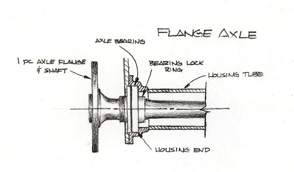
Flange Axle Design
- The most common flange axle design has a single piece
axle, flange and shaft. The axle bearing has a press fit
on to the axle shaft and a bearing lock ring is then pressed
on behind the bearing. Housing ends are welded to the housing
tube and the bearing slips into the housing end. The bearing
is then retained by the caliper mounting bracket. Wheel
studs are installed in the flange of the axle where the
wheel bolts directly to the outside of the axle flange.
With this design the axle and axle bearings must support
not only the vehicle’s weight and torsional loads,
but also the bending loads from acceleration (rear wheels
try to “toe-in” during acceleration).
Safety
- In the event of an axle failure the axle along with the
wheel and tire can separate from the vehicle. In the case
of a break outboard of the bearing, the wheel will definitely
come off. A break inboard of the bearing and the wheel will
stay on only until the caliper mount breaks and the bearing
is free to come out of the housing end. This will also take
out the rear brakes and the caliper and brake lines will
be torn off.

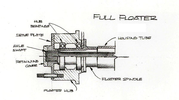
Full Floater Design
- The full floater design incorporates a hub with a bearing
installed in each end. Wheel studs are installed into this
hub and the assembled hub is then slipped on to the floater
spindle. The floater spindle is then welded to the housing
tube. The floater spindles are tubular and are large enough
for the axle shaft to pass through. The drive plate is splined
in the center and slides over the wheel studs and seats against
the hub. The axle shaft is splined on both ends, one end engages
the drive plate and the other end engages spool in the thirdmember.
With a full floater the axle shaft only sees torsional loads
since the wheel and tire are bolted to the floater hubs, which
are independent of the axle shaft. All other loads are taken
in the hubs and floater spindles Safety
- In the event of an axle failure the wheel and tire will
remain with the vehicle (as stated earlier the axle is independent
of the flange and hub which are mounted on the floater spindle).
The rear brakes would not be affected by axle breakage.

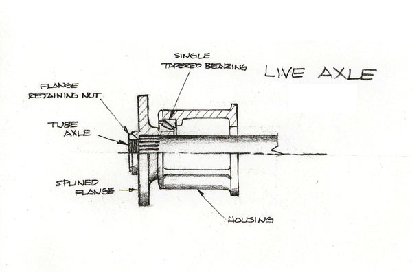
Live Axle Design
- With this design the axle shaft is a large diameter, thin
wall tube and becomes more of a structural member. The shaft
is splined in the center to engage the spool and splined
on both ends to accept a splined flange on each end. Both
ends have a threaded area for the flange retaining nut.
Most live axles use a single tapered roller bearing on each
end, which must be preloaded with the flange retaining nuts
during assembly. This design is most commonly found in Top
Fuel car applications. With this design the axle shaft must
carry all the load.
Safety
- As is the case with the flange axle, in the event of an
axle failure (unlikely due to the size of the axle) the
wheel and tire can separate from the vehicle. This would
also take out the rear brakes and the caliper and brake
lines would be torn off.

Source:
Mark Williams Enterprises
www.MarkWilliams.com
|


